
As electronic products become more compact and more functions are integrated into a single PCB, front-panel indication is becoming more demanding.
A light guide may look like a small mechanical component, but in high-density electronics its design directly affects LED visibility, optical isolation, PCB layout freedom, assembly reliability and the overall appearance of the finished equipment.
High-density designs require more than simply guiding light from Point A to Point B.
When multiple LEDs are placed close together, each optical path must be controlled individually. Mechanical spacing, light isolation, housing structure, PCB position and front-panel alignment all become part of the same design problem.
1. Optical Isolation Becomes Critical in Multi-Position Designs
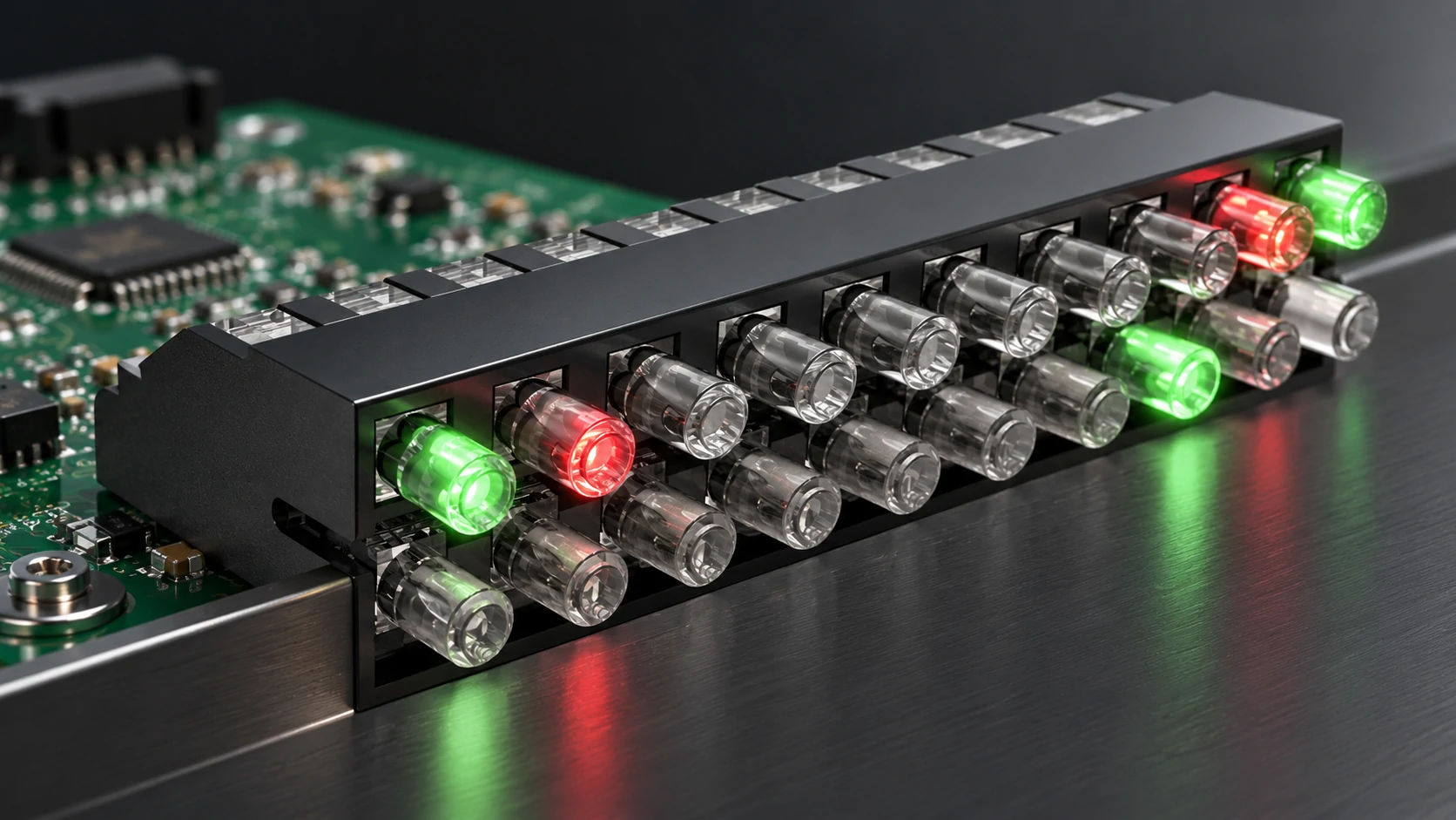
In a multi-position light guide assembly, several LED indicators may be located only a few millimeters apart. Without effective optical separation, light from one LED can enter the neighboring channel, producing visible crosstalk at the front panel.
One practical solution is to combine individual transparent optical paths with an opaque housing that separates each channel. This structure helps keep the indication points visually independent while maintaining a compact overall footprint.
Independent Channels
Separate optical paths help reduce unwanted light leakage between adjacent indicators.
Compact Pitch
Dense multi-position structures can support compact PCB layouts and closely spaced front-panel indicators.
Mechanical Alignment
The light guide, PCB LED position and front-panel opening must remain aligned after assembly.
Repeatable Assembly
Integrated housings and positioning features can simplify production and improve consistency.
2. PCB-to-Panel Distance Is a Mechanical and Optical Parameter
The distance between the PCB-mounted LED and the visible front-panel indication point determines much of the light guide geometry.
A short, straight optical path is relatively simple. However, once the enclosure becomes deeper, the PCB position changes, or the front-panel indicator is offset from the LED, the structure may require a longer rigid path, a right-angle design, or a customized mechanical configuration.
This is why light guide selection should ideally happen together with the enclosure and PCB design, rather than being treated as an afterthought.
Key information for a light guide feasibility review
- PCB LED position and LED package size
- PCB-to-front-panel distance
- Number of indication positions
- Required pitch or spacing between indicators
- Front-panel opening size and geometry
- Straight, right-angle or offset routing requirement
- Existing part number, drawing or physical sample for replacement projects
3. Standard Light Guides Are Not Always the Best Fit
Standard light guide products are useful when the PCB position, panel geometry and indication layout already match an available structure.
But many industrial products are constrained by existing PCB layouts, enclosure dimensions or legacy component footprints. In these cases, forcing the design around a standard component can create unnecessary mechanical compromises.
A customized light guide allows the optical path, housing structure, mounting method, number of positions and output geometry to be designed around the actual equipment.
Replacement Development for Existing Light Guide Parts
For customers already using an existing light guide, a replacement project does not always need to start from a completely new design.
An existing Bivar-, Mentor- or VCC-style part number, technical drawing, sample or PCB/front-panel information can be used as the starting point for dimensional review, optical-path analysis, manufacturability assessment and sample development.
4. High-Density Light Guide Design Is Also an Assembly Problem
The best optical design still needs to work reliably on the production line.
Multi-position assemblies must maintain channel spacing, stable positioning and repeatable alignment after soldering and enclosure assembly. Housing features, mounting legs, positioning structures and optical-body retention all influence the final production result.
For this reason, optical performance, mechanical design and injection-molding manufacturability should be evaluated together during development.
Typical Application Areas
TOPTEN Light Guide Development Support
TOPTEN focuses on PCB-to-panel light guide solutions for industrial electronics, including standard and customized single-position and multi-position structures.
Have a Light Guide Application to Review?
Send us an existing part number, drawing, PCB layout, front-panel photo or key dimensions. Our team can review the structure and discuss a suitable standard or customized light guide solution.
Contact TOPTEN Light Guide