
Technology
Light guide performance is determined by both optical design and structural engineering. Our technology focuses on precise light transmission, channel isolation and reliable mechanical integration, enabling stable visual indication in high-density industrial electronics.
Optical
Principle
Comprehensive range of light guide solutions for diverse industrial needs
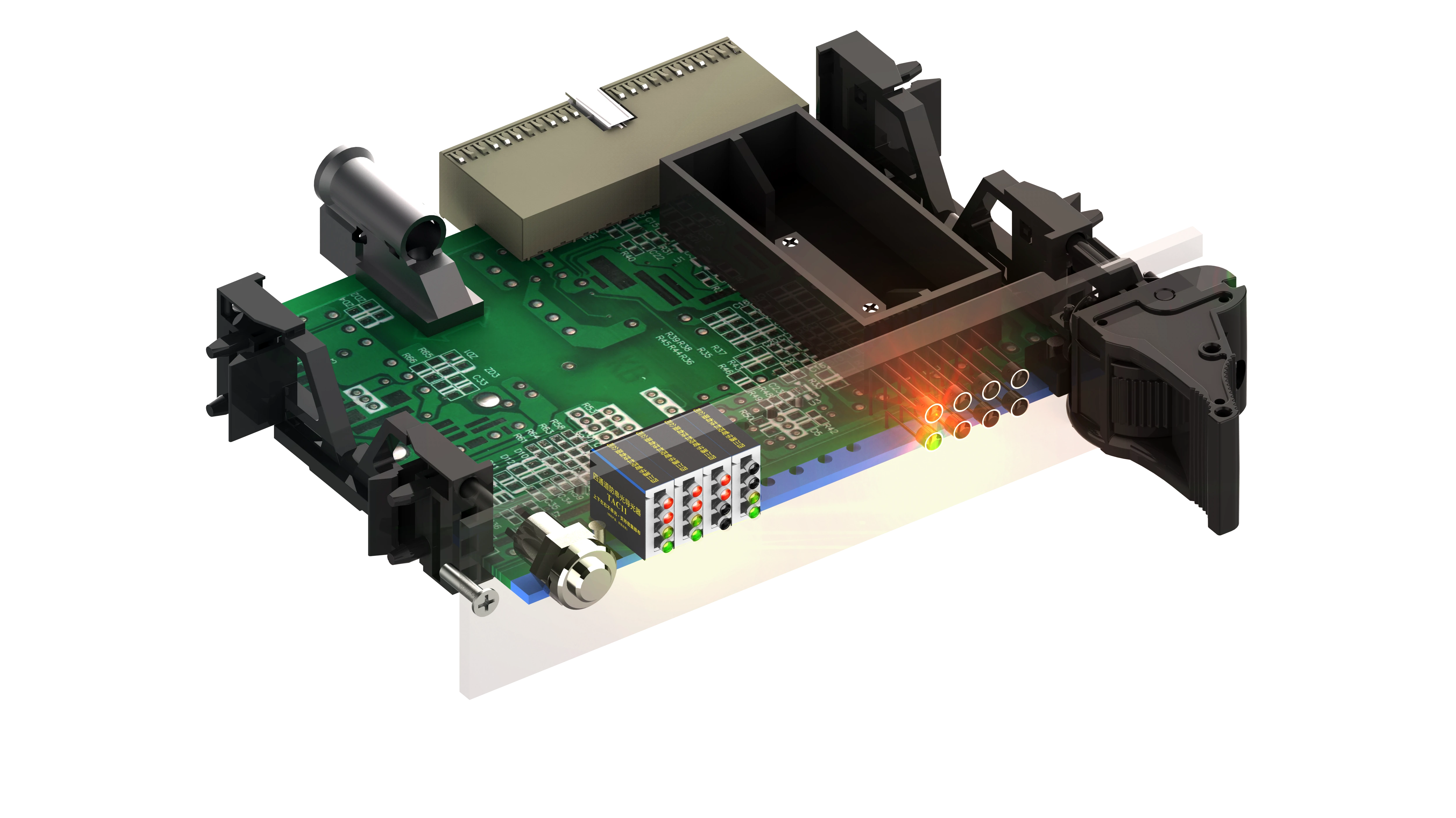
Light guides are optical components that transfer light from PCB-mounted LEDs to visible indicators on the front panel of electronic equipment. By creating a controlled optical path, they allow designers to separate the LED position from the display position while maintaining clear indication, efficient light transmission, and compact system architecture. This makes them especially valuable in industrial electronics where space, visibility, and layout flexibility are critical.
ANTI CROSSTALK DESIGN
Optimized optical channel structure prevents light leakage between adjacent indicators.
HIGH DENSITY LAYOUT
Supports dense LED spacing such as 2.54 mm pitch and compact indicator panels.
PRECISION OPTICAL SURFACES
Controlled optical surfaces ensure stable light transmission and uniform illumination.
OPTIMIZED PIN DESIGN
Engineered pin structures improve installation stability and reduce PCB tolerance sensitivity.
Anti
Crosstalk
Precision Optical Isolation for High-Density Industrial Indicators
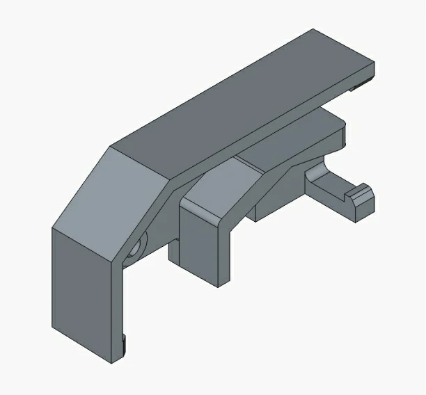
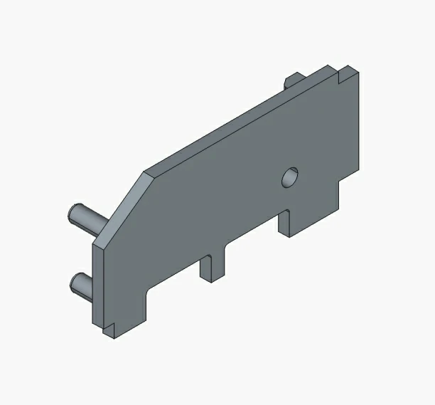
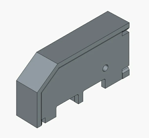
High
Density
Compact Multi-Channel Light Guide Solutions for Space-Constrained Designs
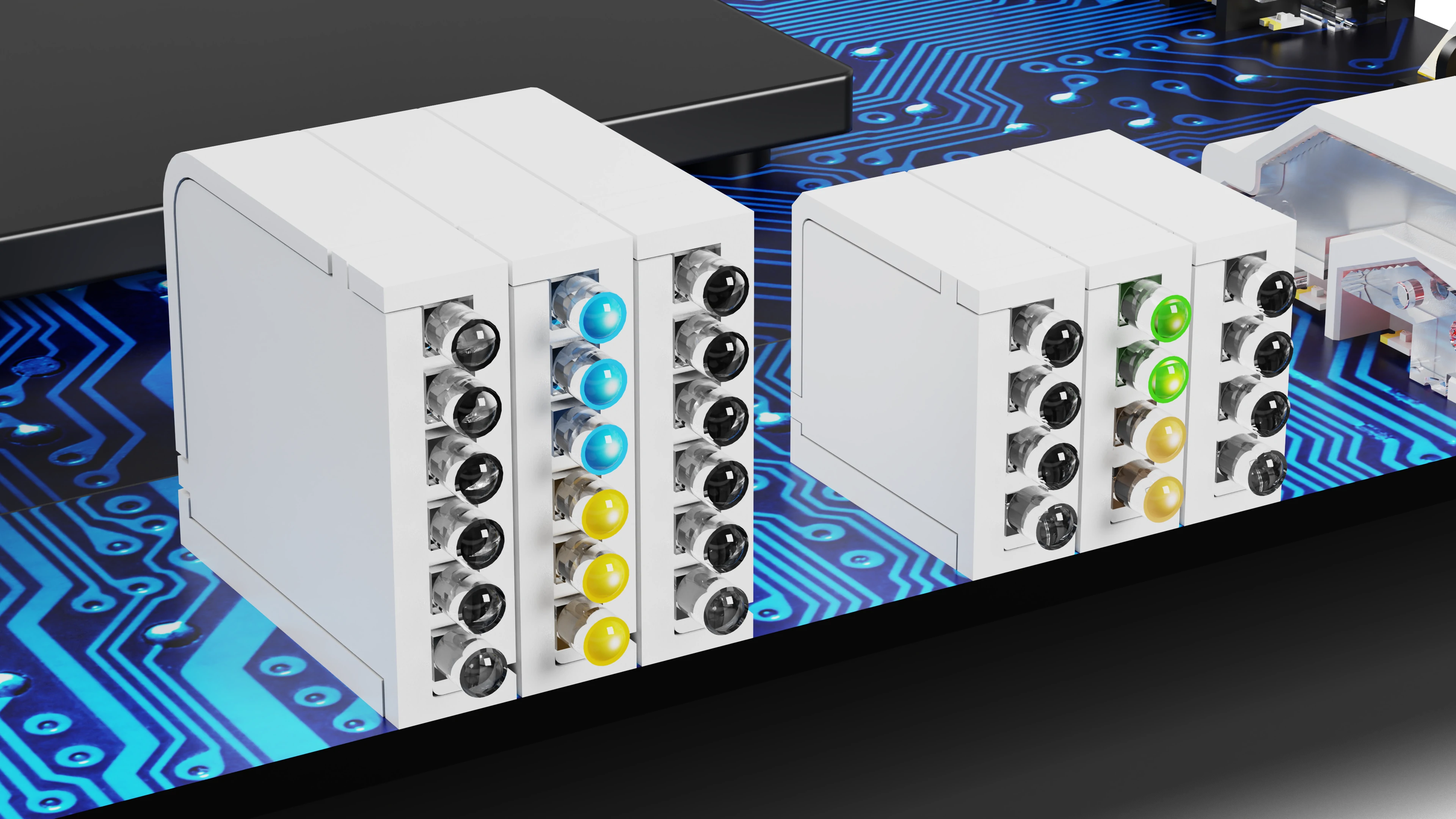
Modern industrial electronics increasingly require compact indicator modules capable of displaying multiple signal states within limited front-panel space.
High-density light guide structures make it possible to integrate multiple indicators into a small area while maintaining clear light separation, consistent visibility, and a clean panel layout.
Optimized optical geometry helps maintain uniform brightness and a consistent visual appearance across all indicator positions.
Reliable
installation
Tolerance-Friendly Pin Designs for Stable and Efficient Assembly
Reliable installation is a critical aspect of light guide design. During assembly, variations in PCB hole diameter, hole position, or insertion alignment can affect mounting stability and optical consistency.
Topten light guide products incorporate specialized pin geometries to accommodate different assembly conditions. Each structure is engineered for specific installation scenarios, tolerance ranges, and mechanical requirements.
Conical Pin
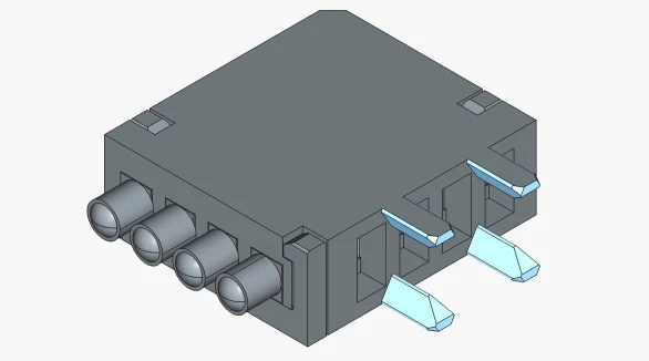
- •Small mounting holes
- •Limited assembly space
- •Fast insertion and alignment
- •Compatible with smaller panel or PCB holes
- •Smooth insertion reduces assembly resistance
- •Suitable for fast and high-volume assembly
Slotted Cylindrical Pin
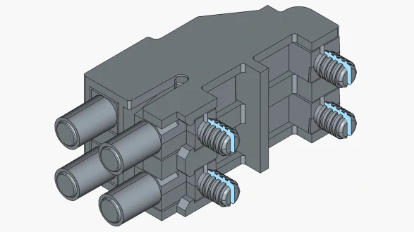
- •Multi-position press-fit installation
- •Assemblies with multiple mounting pins
- •Modules requiring improved tolerance adaptability
- •Slot design relieves assembly stress
- •Reduced sensitivity to hole diameter and alignment tolerances
- •Helps maintain module geometry and optical alignment
- •Easier installation and removal
2nd Generation Reinforced Thread Pin
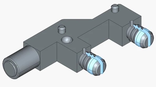
- •Industrial environments exposed to vibration or shock
- •Applications requiring stronger panel-to-PCB retention
- •Critical status indication modules that must remain secure
- •Improved thread strength and structural stability
- •More secure mounting on PCB
- •Suitable for high-vibration and long-term industrial use
Why Slot Design Improves Assembly Tolerance
TPT pin designs are engineered for industrial assembly requirements, delivering greater tolerance flexibility, easier installation, and long-term mechanical reliability through slotted and reinforced structures.
Optical
Surface
Controlled Surface Finishing for Consistent Optical Performance
The optical performance of a light guide depends not only on its geometry but also on the quality of its optical surfaces.
Controlled mold design and precision surface finishing help ensure consistent light transmission, defined output, and stable illumination across high-volume production.
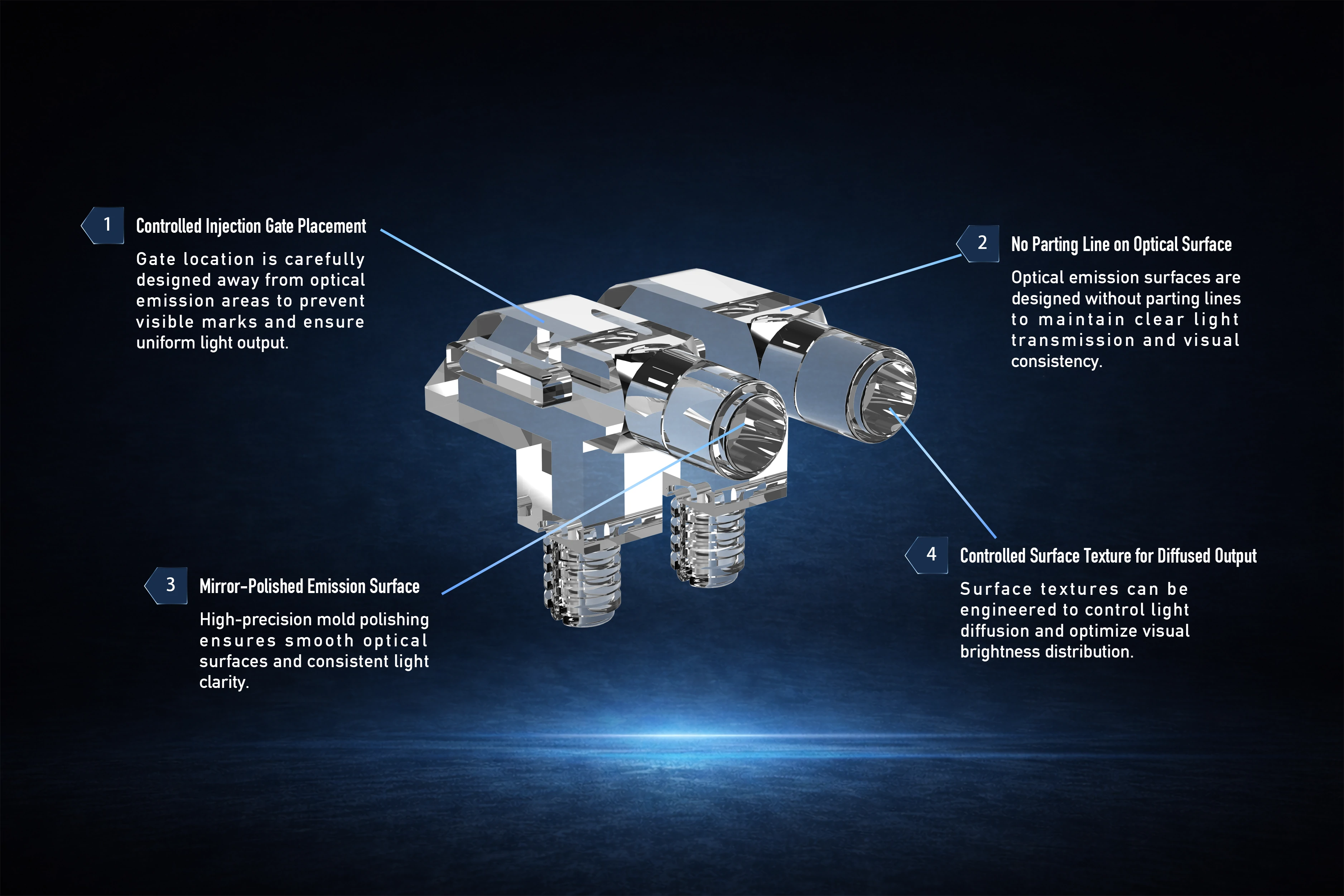
Gate location is positioned away from critical optical emission areas to reduce visible marks and support more uniform light output.
Optical emission surfaces are designed to avoid parting lines, helping maintain clear transmission, cleaner appearance, and consistent visual output.
High-precision polishing improves surface clarity and supports stable, well-defined light transmission at the viewing end.
Surface textures can be engineered to manage light diffusion and help optimize brightness distribution for a more uniform visual effect.
- •Controlled injection gate placement
- •Avoidance of parting lines on optical surfaces
- •Mirror-polished emission areas
- •Consistent surface texture for diffused output
These manufacturing controls help ensure stable optical performance, consistent light output, and reliable visual quality in high-volume production.
3-Step
Engineering Process
Work with our engineering team to quickly define and develop the right light guide solution for your application.
Submit Your Requirements
Send us your light guide requirements through the contact form or reach out to our team directly.
Engineering Evaluation
Our engineering team reviews your requirements and provides professional technical recommendations.
Solution & Quotation
Receive a tailored light guide solution and quotation to move forward with your project.
Ready to Illuminate Your Products?
Discuss Your Light Guide Project